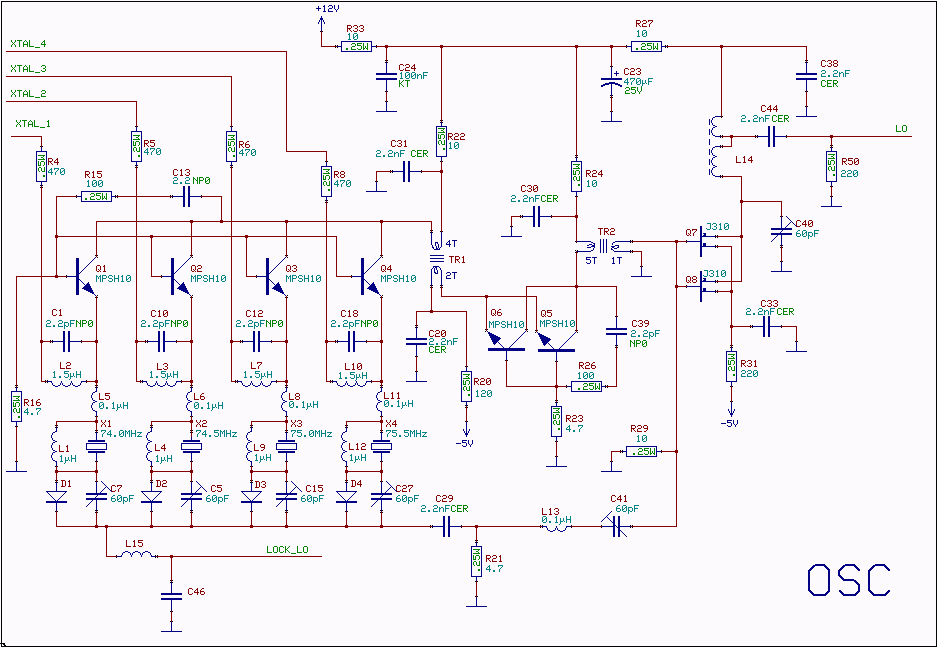
A series resonance X-tal oscillatorThe oscillator is similar to the oscillator used for conversion from 10.7 to 2.5 MHz. but there is no frequency divider at the output and impedance matching to the low impedance of the crystel is made with transformers rather than with tuned circuits to allow for the larger frequency range needed here.An oscillator can be seen as an amplifier which has feedback through a filter. The amplifier of a series resonance oscillator must have both a low input impedance and a low output impedance, preferrably well below the series resonance impedance of the X-tal, to preserve the selectivity associated with the high Q of the X-tal itself. The frequency is adjusted with a trimmer in series with the X-tal.
|

The frequency is adjusted with a trimmer in series with the X-tal.
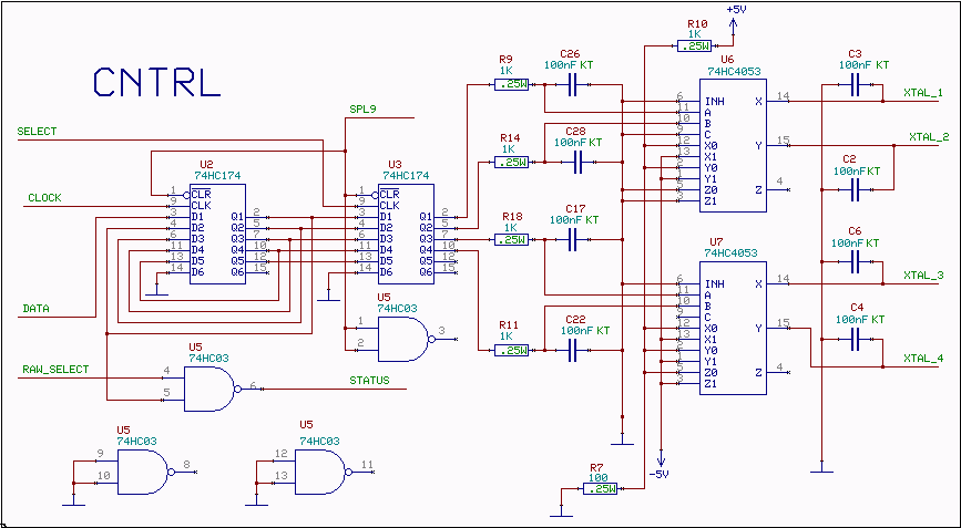
Select(input)
Clock (input)
Data (input)
Status (output, open collector)
These pins are intended to be connected directly to the parallel port of the PC for small systems, one separate data pin for each select input with all the other pin's in parallel. Larger systems need a decoder to convert 6 pin's to one of 64 pin's.
The frequency control is level controlled and all wires are well decoupled to avoid sending interference into the oscillator. The user program is responsible for setting the d-type flip-flops right so only one of the 74HC4053 outputs is at minus 5 volts while the other four are at plus 5 volts.
