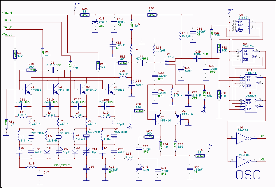
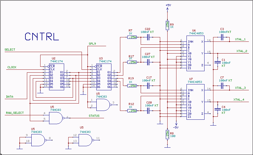
linrad support: The local oscillator for 10.7 to 2.5MHz conversion.
(April 22 2004)

A series resonance crystal oscillator

A 52 MHz third overtone crystal is typically 30 ohms at its series resonance according to manufacturer specifications. The crystals used for the prototypes have nearly ten times lower series resistance but they were very expensive.

The oscillator is in a way similar to the oscillator used for conversion from 2.5MHz to the baseband I and Q.

An oscillator can be seen as an amplifier which has feedback through a filter. The amplifier of a series resonance oscillator must have both a low input impedance and a low output impedance, preferrably well below the series resonance impedance of the crystal, to preserve the selectivity associated with the high Q of the crystal itself.

Since this oscillator is used at a higher frequency the amplitude of the oscillations is controlled by a limiter to make the transistor run in class AB. This gives a good compromise between the wideband noise floor and the close in phase noise.

Class C is good at low frequencies but a bad idea for VHF oscillators, particularly if they are intended to be used to generate microwave frequencies. Class A amplifiers give the best close in performance and should be used for microwave frequency multiplier chains.

Here is some information about state of the art VHF crystal oscillators

The complete circuit diagram is shown in fig. 1. Only one of the MPSH10 transistors is conducting, the others are blocked by having +0.5V at the emitter.


Fig.1. Schematic diagram for the 53MHz crystal oscillator that produces a squarewave LO signal at 13MHz.


The output impedance of the selected MPSH10 transistor is stepped down by a factor of about 20 in a LC resonant circuit. The coil, L14, is 5 turns of 1.2 mm enameld wire. The coil is wound on a 7 mm rod and mounted self supporting on the PCB with a distance from the copper to the PCB of 3 mm. The length of the coil is 11 mm. It is essential to feed the amplifier Q5 from a low impedance to make the noise generated in this transistor low. The MPSH10 transistor generates very little noise because of the large current feedback on the emitter. Except at the frequency of series resonance the impedance seen by the emitter is high and loss-less.

The frequency of oscillation is adjusted with a trimmer in series with each crystal and provision is made to add a diode to allow locking the oscillator to a frequency standard.

The active MPSH10 transistor is driven into class AB by the power coming through the crystal. The emitter resistor is connected in series with a 1.8 microhenry inductor to not allow the emitter to see the resistor and the noise from it at large distances from the center frequency. Adding this inductor makes a clear improvement at a frequency separation of 100kHz. The small inductor between the emitter and the crystal compensates for the tuning capacitor to get the correct frequency of oscillation. It also isolates the emitter from the stray capacitances of the crystal.

Some feedback is made from collector to base to prevent UHF oscillations, the collector tuning capacitor is isolated from the collector through a small inductor in parallel with a resistor to allow a collector voltage for this feedback at UHF frequencies.

Selecting crystal

The oscillator is selected by a simple low speed serial interface that is adopted for all Linrad hardware. Each unit has four communication pin's.

Select(input)
Clock (input)
Data (input)
Status (output, open collector)


These pins are intended to be connected directly to the parallel port of the PC for small systems, one separate data pin for each select input with all the other pin's in parallel. Larger systems need a decoder to convert 6 pin's to one of 64 pin's.

The frequency control is level controlled and all wires are well decoupled to avoid sending interference into the oscillator. The user program is responsible for setting the d-type flip-flops right so only one of the 74HC4053 outputs is at minus 5 volts while the other three are at plus 5 volts.


Fig.2. Frequency control.

Frequency stability of RX10700

At a low frequency like 10.7 MHz, frequency stability is good without locking the local oscillator to a frequency reference. Figure 3 shows about 80 minutes of typical behaviour with a warmed up unit. The test signal is from two different HP8657A signal generators which were combined in a hybrid and fed into channel 1 of an RX10700 prototype unit which was connected to a RX2500 unit which in turn was connected to a Delta44 board sampling at 24kHz. The short term frequency stability of the Linrad hardware is comparable to or better than the stability of the HP generators.

The short time frequency drift is probably below 0.02 Hz/min. An earlier RX10700 prototype with a class C oscillator had a short time frequency drift of about 0.05 Hz/min. The short time frequency stability determines how narrow bandwidths one might use for detecting really weak signals.


Fig.3. Frequency stability. Two different 10.7 MHz signals derived from HP8657A signal generators are fed to the input. Most of the short term instabilities are probably due to the influence of varying mains voltage on the HP generators.