| |||||||||
| Figure 1. A simple pulser for Linrad calibration. | |||||||
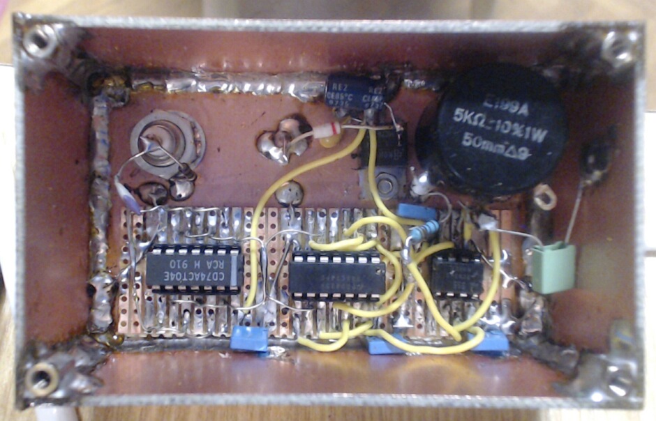
Make sure to provide good decoupling of VCC on all the ICs. The 555 makes a negative transition between each positive one that changes the state of the 74AC74. Good filtering makes those pulses negligible on the output. Those weak pulses could give false results if they had a very precise separation from the main pulse. The 555 has enough phase noise to ensure that this is not a problem above about 10 MHz. In case lower frequencies are of interest one could increase the phase jitter on the 555 by adding a noise source through a resistor in series with a capacitor into pin 5 of the 555 or run the 555 slower (or both.) The spectrum of the pulse generator should not be narrow peaks representing the odd overtones of the squarewave. The spectral lines should be broadened by noise so the difference between maximum and minimum is small. For most hardware this does not matter, but in some cases with very sharp analog filters the ringing of the filter could extend halfway between pulses. The 0.33 uF capacitor is suitable for hardware like the IQ+ and many others, but to make it fit all types of hardware one has to modify the the unit by adding two switches that control the capacitor value. Both open: C = 0.047 uF One closed: C = (0.33 + 0.047) uF Both closed: C = (2.0 + 0.33 + 0.047) uF Figure 2 shows a photo before the switches were installed. | |||||
| |||
| Figure 2. A nice PCB is not required. | |