For full class C drive (80mA grid current at -400V) this grid circuit needs about 120W drive power.
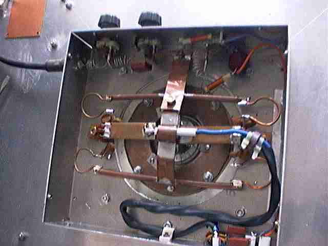
The photo shows the grid compartment of the QBL5/3500 amplifier
I currently use.
Slitted tubes (A brass tube that fits the pins is cut in several
planes parallel to the axis) form connectors that fit the pins of the
QBL tube.
The wall thickness of the slitted tube is about 3mm and each is
about 15mm long.
The 4 slitted tubes are soldered to copper strips made from 3mm copper
(about 25mm wide).
In this way each tube pin is thermally well connected to a large cooling
area that works as tube connectors.
The two grid connecors are joined by a thin (flexible, about 0.25mm) copper sheet that is bent above the bunch of decoupling capacitors that decouples between the cathode pins.
The tube is pressed against the anode connector by the screen grid connector which is the circular copper sheet surrounding the tube. The screen grid connector is bolted to the screen grid capacitor with 4 nuts. the screen grid capacitor is a copper plate with grounded aluminium plates on each side isolated by 0.5mm polypropylene. WARNING: the screen grid capacitor is also a resonator!!! It has to be small enough to have its parallel resonance well above 144MHz (mine is 4 by 4 decimeters or so). The distance from the screen grid to the end of the capacitor plate should be about a quarter of a wavelength to form efficient grounding of the screen grid by a series resonance.
Near each end of the heater strips a copper strip is bolted to the aluminium chassis. The heater connectors are decoupled to these ground connections while the heater current is applied through a twisted pair of 6 square mm ordinary PVC insulated wire. (The PVC is replaced by teflon under the grid strip - PVC would melt by RF heating in the strong electric field here). The twisted heater wire goes through a ferrite toroid (probably not needed). At the end of each grid connector is a copper tube, about 2dm in length. These tubes are lengthened by small loops at each end to form 4 parallelled inductors from grid to ground. Each of these loops is decoupled to the same earth points as the heater. The copper tubes provide additional cooling and make the whole "connector" arrangement mechanically stable.
The drive power is applied through a LCLC network that steps up the voltage and allows fine tuning of the grid resonance. One more LC link (further right) provides a 180 degrees twisted voltage that is connected to a wire going into the plate cavity to provide neutralisation (both L and C has to be tuned for neutralisation)
The cathode/grid connector is removed by removing 3 nuts. The whole assembly can then be lifted and placed upside down on the cavity outside the grid compartment. (The flexible strip from the LCLC network is first bent away)
The screen grid connector can be lifted straight up after 4 more nuts are removed. The actual connection is from finger stock all around the tube while the pressing down is done by the 3 stainless steel "fingers" that can be seen on the photo.
When the screen grid connector is removed, the tube can be pulled out from the anode connector (home made finger stock)
The aluminium lid which normally covers the grid compartment does not affect the tuning at all. For several years I did not use it until I got complaints about radiation of overtones on 70cm. Putting the lid properly in place reduced the signal level from S7 to nearly unaudible at 432MHz as reported by SM0DFP about 80km away.