The linear noise blanker vs the ordinary noise blanker
A noise pulse such as an ignition spike from a car or a single pulse in a pulse train produced by a power line is very short, in general much shorter than 1 microsecond. This means that the interference noise pulses are wideband pulses, covering a frequency range that is much wider than the receiver bandwidth.When a noise pulse passes through the selective filters of the receiver, the shape of the pulse at the receiver output is entirely created by the filter response of the receiver.
The linear noise blanker is a separate receiver function within the software that receives noise pulses using adaptive polarisation to get the best possible S/N for the noise pulse. With optimum S/N the time, phase and amplitude for the pulse can be accurately determined. Once the pulse is accurately known it is possible to calculate exactly how this pulse contributes to the total signal in some other polarisation, particularly the polarisation selected for receiving the desired weak signal.
Knowing exactly how a particular pulse contributes to the noise in the interesting polarisation means one can subtract the entire pulse from the noise in the normal receive channel INCLUDING PARTS VERY NEAR OR BELOW THE NOISE FLOOR. Subtracting a pulse from the noise will not in any way modulate sine waves present in the pass band, so no keying clicks are produced. That is why I call this strategy "the linear noise blanker"
A "normal" noise blanker will just clear (make zero) all points above a certain threshold. The tails of a pulse will normally not be removed. Of course it is possible to clear a few surrounding points to remove the tails, but then some more of the desired signal is unnessecarily lost, which matters at high pulse repetition frequencies. All cleared points will of course clear the contributions from sine waves in the pass band which is the same as amplitude modulating them, causing keying clicks.
Practical implementation
The routine run_normal_blanker( ) in BLANKER.C finds regions where the noise is above the first threshold T0 = blanker_threshold.By a call to the routine blanker_poltransform( ) the polarisation for the noise pulse is calculated assuming all the noise in the region that is above the threshold has a common origin. The signal pair (from the two X-yagi polarisations) is then transformed to a new signal pair. One that contains the interference and another that hopefully contains only white noise at the normal noise floor.
After locating the largest point in the within the region in the polarisation of the noise source, run_normal_blanker( ) then calls the routine subtract_pulse( ) which makes a 4 point fft using the largest, the second largest and one point outside each one of them as input.
The phase slope of the transform is used as index for a table of standard pulses that are calculated from the total frequency response of the whole receive system during blanker initialisation. The standard pulse is then subtracted from the two antenna signals with the appropriate amplitude, phase and polarisation.
The largest point in the remaining data is located, and if it is above the threshold one more pulse is subtracted until all points are below the threshold or until too many pulses have been subtracted. Any points that still are above the threshold is treated with a normal blanker i.e. is made zero.
Real life performance
Due to the extraordinary weather (rain always) in 1998 no powerline noise has been present since the noise blanker became operational.The blanker removes car ignition noise completely, but that is a minimum requirement for a noise blanker that is easily fulfilled by a normal blanker. Once the insulators of the nearby 10kV power line dry up I will place some graphs here that illustrate how the noise blanker of the PC radio works. The real test will be during a contest with many strong stations and with strong powerline pulse trains. During such circumstances no other noise blanker will enable receiving of weak signals.
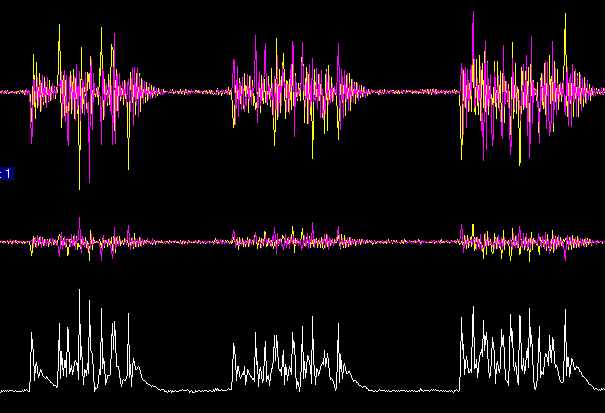
The interference from a 50Hz power line is typically pulse trains that occur at a repetition rate of 100 Hz. The length of each pulse train, and the separation between the pulses within the pulse train varies. In fig 3. the pulses have a repetition frequency of about 2kHz within each pulse train. A conventional noise blanker that could remove this kind of interference needs a gaussian like filter with a rather large bandwidth to resolve the individual pulses. When pulses are separated by only 0.5 milliseconds (2kHz), the time during which the receiver should need to be blocked should be in the order of 50 microseconds, which means that the 3dB bandwidth has to be about 20kHz or more. Such a blanker is useless during a contest or band opening because then strong signals within the pass band can not be avoided.

Fig 1. Power line noise as seen by the PC radio without any digital correction filter in the PC (data recorded in the dry summer 1997). The bandwidth is 20kHz, the upper track is one polarisation (re_h and im_h) , the second track is the other polarisation (re_v and im_v). The two colours are the real and imaginary parts of the signal. The lower track is total power, i.e. the sum of the squares of all four voltages re_h, im_h, re_v, im_v.
With the correction filters set up by the blanker initialisation routine the individual noise pulses within each pulse train will be well separated.
IF THE PROGRAMMING IS CORRECT, THE PC RADIO SHOULD ELIMINATE THIS KIND OF INTERFERENCE COMPLETELY EVEN WHEN SEVERAL STRONG SIGNALS ARE PRESENT IN THE PASSBAND