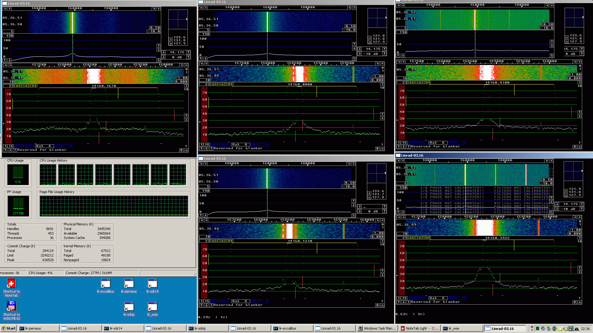
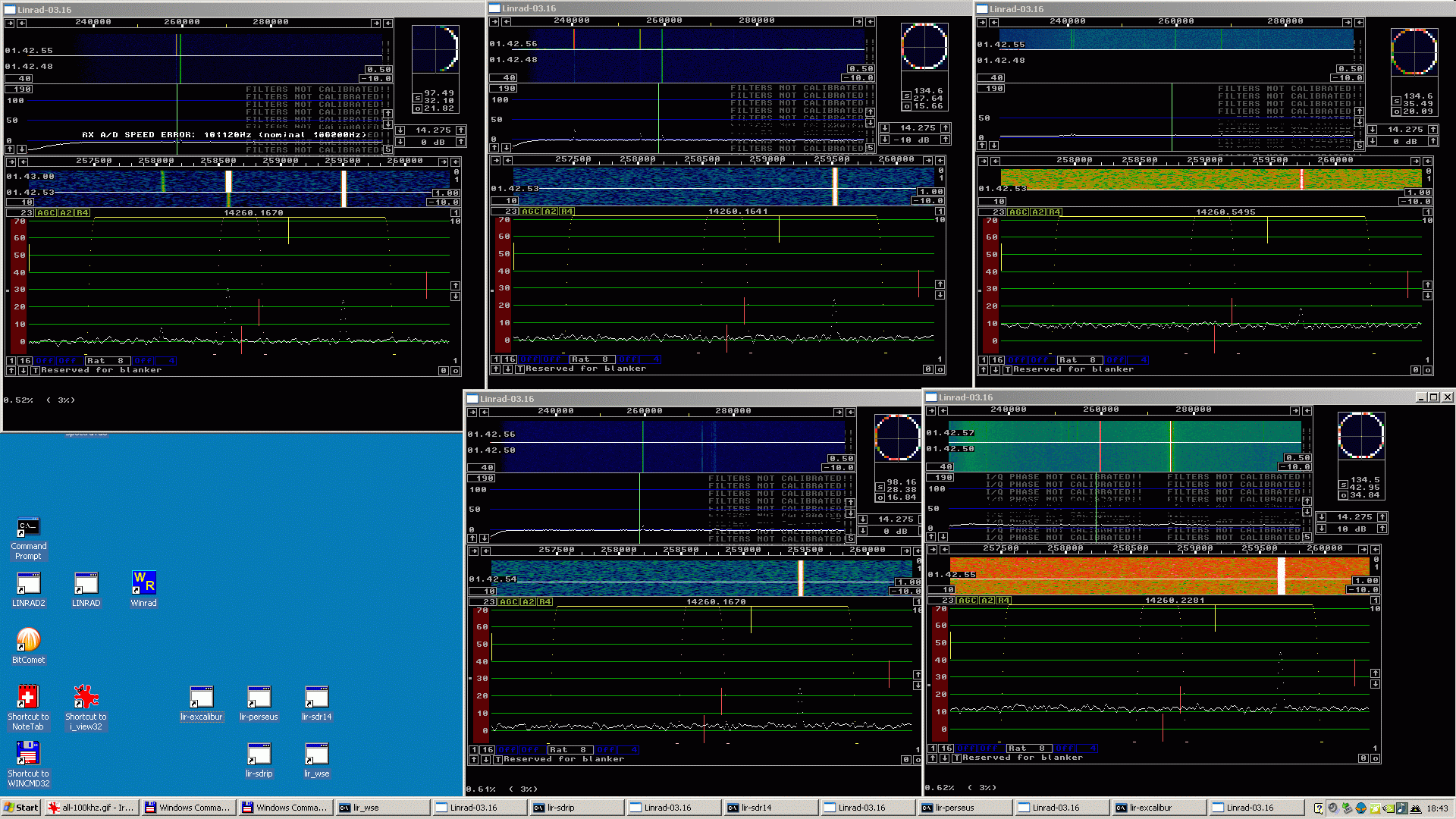
Comparisons at 96 or 100 kHz sampling speed.Figures 1 and 2 show SDR-14, Perseus, SDR-IP(option 01), Excalibur and the WSE converters with Delta 44 receiving on 14.16 MHz. The signal is generated by a crystal oscillator with very low phase noise about -180 dBc/Hz at a frequency separation of 10 kHz.The signal was sent to a resistive splitter that was followed by attenuators that were used to set all the SDRs to within 1 dB of saturation. The Linrad parameter "First FFT amplitude" was set to make the S-meter reading identical, 127.9 dB. With identical parameters for the first FFT bandwidth and size that places the signal at the same level in the main spectrum. The colour scale for the waterfall is the same in all five instances of Linrad so the noise floor (reciprocal mixing from the sampling clock and A/D converter noise) can be compared directly. There is a second signal about 1 kHz above the strong signal in figure 1. This signal is at the same level in all receivers as a consequence of having set the S-meter reading identical for the main signal. In figure 2 the extra signal is shifted upwards by 101 kHz. The center frequencies of all the SDRs is also shifted upwards by 100 kHz and the colour scale is shifted by 10 dB. The four entirely digital radios are still 1 dB from saturation while the WSE system is far from saturated. The front end attenuator/amplifier of the WSE system is therefore changed by 20 dB. From -10dB to +10 dB. |
|
|
| Fig 1. Upper windows from left to right: Excalibur, Perseus and SDR-14. Lower windows from left to right: Task Manager, SDR-IP and WSE. The signal 1 kHz above the strong signal is (as expected) at the same level, about 24 dB on the baseband dB scale. The noise floor is similar in Perseus, SDR-IP and WSE while the 1kHz dynamic range is about 5 dB worse in SDR-14 and about 8 dB worse in Excalibur. |
|
| Fig 2. Upper windows from left to right: Excalibur, Perseus and SDR-14. Lower windows from left to right: Nothing, SDR-IP and WSE. The signal 101 kHz above the strong signal is (as expected) at the same level, about 24 dB on the baseband dB scale as in figure 1. In the WSE window it is at 44 dB because of the 20 dB higher gain while it is at 19 dB in the SDR-14 because of the 16 bit limitation in the USB link. Excalibur,Perseus and SDR-IP are similar, The WSE system is about 10 dB better while the SDR-14 is about 13 dB worse. (The SDR-14 suffers from signal loss and quantization noise due to the 16 bit limitation of the USB interface.) The lower part of the waterfalls is with 20 dB attenuation on the strong signal. |
|
The Excalibur is at about -153 dBc/Hz at 100 kHz. From figures 1 and 2 one can make this table: |
  Unit         BDR at 1 kHz          BDR at 100 kHz
                  (dBc/Hz)               (dBc/Hz)
Excalibur           134                    153
Perseus             141                    152
SDR-14              138                    139
SDR-IP              141                    151
WSE                 141                    161
|
|
Table 1.Approximate dynamic range figures obtained
from figures 1 and 2.
The SDR-14 is limited by the 16 bit transfer of the USB link so
the dynamic range data might not be very useful.
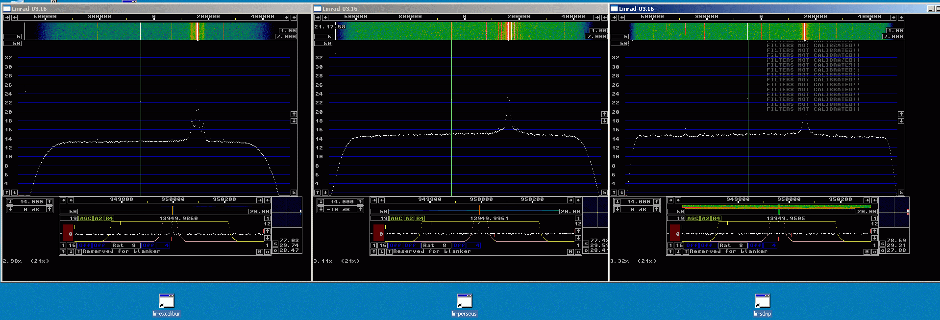
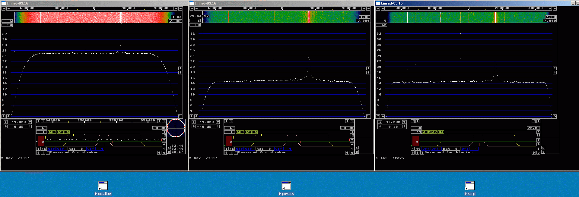
Figure 2 shows the noise floor without the strong signal in the lower part of the waterfalls. In the SDR-14 there is no signal at all because the weak signal and the noise have an amplitude that is less than 1 bit on the USB link. (The strong signal is outside the passband.) The Excalibur has a fairly strong spur 100 kHz from the main signal and one can see that the noise floor is a little (about 1 dB) lower with the strong signal attenuated so some phase noise is present. The Perseus and the SDR-IP show no sign of spurs or phase noise while the WSE system has its noise floor about 2 dB lower without the strong signal. The purpose of this page is not to provide accurate performance tables but to show a real life side by side comparison. Make your own judgement of the accuracy by studying the images. Comparisons at 1 MHz sampling speed.Figures 3 and 4 show show spectra at a sampling rate of 1 MHz with the same strong signal as used for figures 1 and 2. The weak signal is stronger and set to 13.95 MHz. Figure 3 is without dithering while figure 4 is with dithering.From figure 3 one can conclude that the noise floor of the Excalibur is about 1.5 dB lower than the noise floor of the Perseus and the SDR-IP at wide separations. The Excalibur has about 20 dB of close range sideband noise. From figure 4 one can conclude that dithering does not change the noise floor in Perseus or SDR-IP while it degrades the noise floor seriously in the Excalibur. In situations where dithering would help to remove some false signal one should not use the builtin dithering of the Excalibur in cases where the degraded noise floor (by about 12 dB) would affect S/N of the desired signal. It would be much better to inject an extra signal into the antenna input for dithering. That signal could be a FM modulated signal generator well outside the desired frequency range with a notch filter that would prevent it from adding any noise at the frequency range of interest. |
|
| Fig 3. From left to right, Excalibur, Perseus and SDR-IP (with option 01) The same signal is fed to all three receivers at 1 dB below saturation. The units are run without dither. The noise floor is a little lower in the Excalibur at wide separations but somewhat higher at close range. |
|
| Fig 4. From left to right, Excalibur, Perseus and SDR-IP (with option 01) The same signal is fed to all three receivers at 1 dB below saturation. Dithering destroys the dynamic range of the Excalibur but does not affect the noice floor noticeably on the Perseus or SDR-IP. |
|
The attenuators needed to make the point of 1 dB compression equal is listed in table 2. |
Unit Attenuation Saturation
(dB) (dBm)
Excalibur 10 -4
Perseus 10 -4
SDR-14 1 5
SDR-IP 9 -3
WSE 23 -17
|
This page is intended to show qualitative differences between the different SDR receivers in the situation where a single strong signal limits the performance in receiving weak signals. Two major phenomena can be observed. The inadequate number of bits in the SDR-14 USB link and the serious degradation of the noise floor in the Excalibur when dithering is used. To SM 5 BSZ Main Page |