Improving the noise floor of a Delta44 A/D converter. Measurements.
(Sept 3 2002)
When placing the computer in a metal box to avoid radio interference a lot of low frequency interference, 1kHz and down enters the Delta44 if the screen of the cable from the Delta44 is allowed to be in electrical contact with the wall of the box. This is an indication of significant potential differences between different parts of the (double) metal case surrounding the computer.

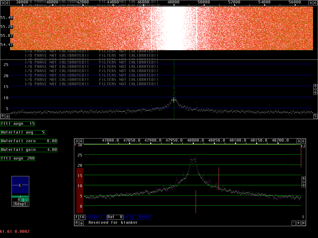
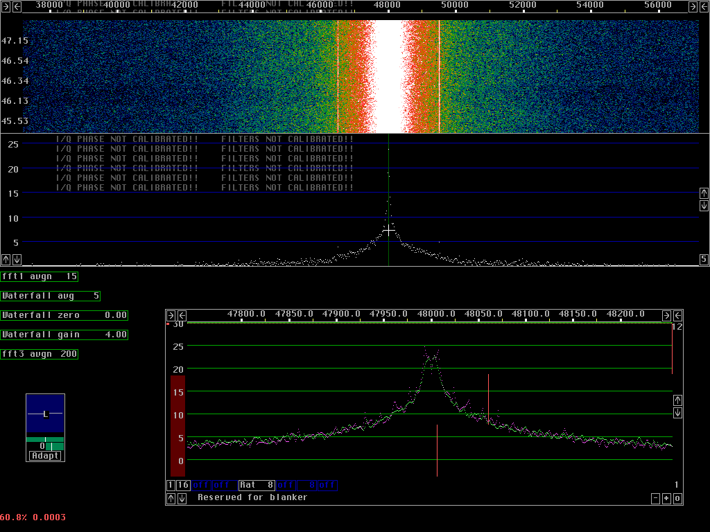
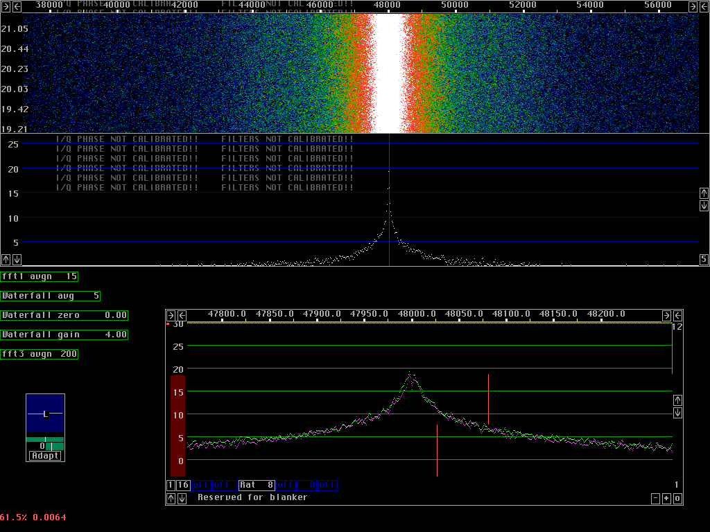
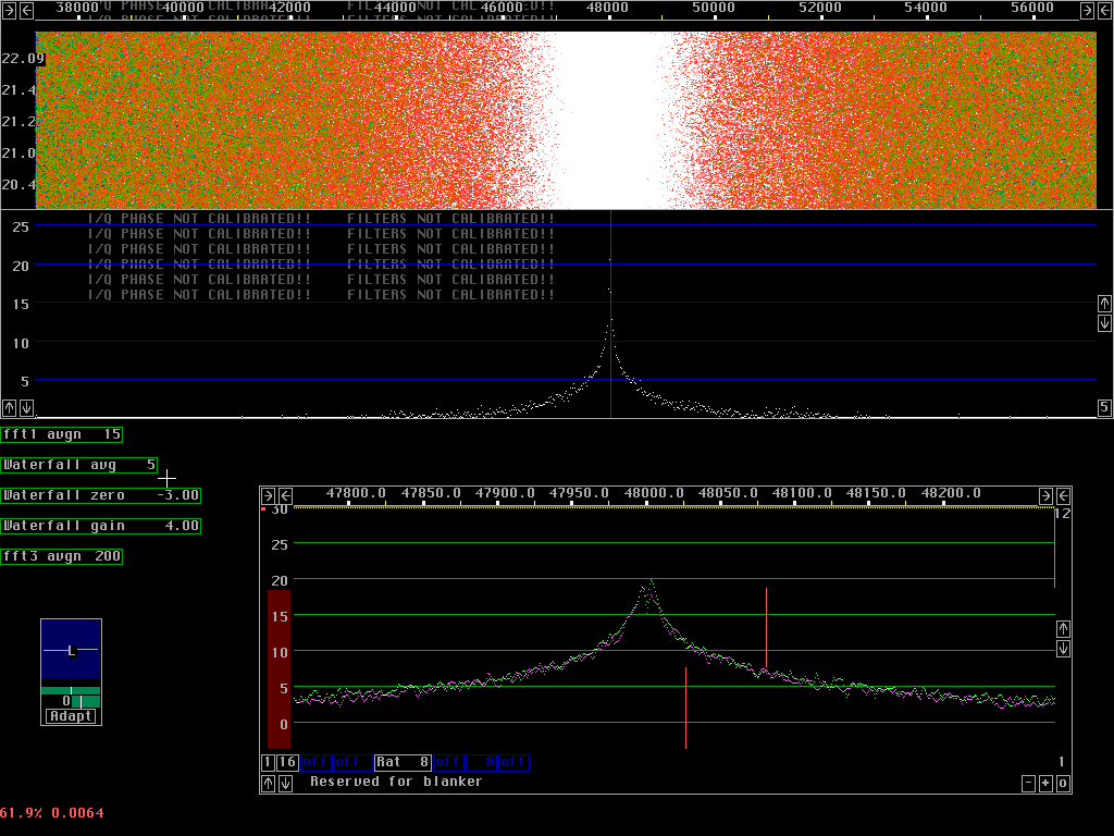
Some of this interference is present also when nothing is connected to the Delta44 or when the inputs are grounded right at the d-sub connector of the board.

Before taking proper action to avoid currents on the screen of the audio cable I decided to try to understand how the interference reaches the input when nothing is connected and to eliminate the interference if possible.

There are three different modifications which together eliminate the low frequency spurs and lower the noise floor by a little more than 3dB. When using Delta44 as the A/D converter for a software radio 3dB is a significant improvement so it is worthwile to do these simple modifications. The board is labelled M-AUDIO DELTA 1999 Rev-B

Fig. 1 shows the Delta44 in its original shape. Figures 2 to 4 show the effect of the modifications when they are added one by one. Figures 1 to 4 have the same colour scale in the waterfall graph while Fig.5 shows the board in its final state, same as fig.4 but here the zero point of the waterfall graph is changed by 3dB to give a quantitative measure of the qualitative differences shown in the previous figures.

The noise floor can be lowered by one more dB by bypassing the input circuitry of the Delta44.

Here are some measurements on the dynamic range of modified Delta 44 showing the performance when the input amplifier/filter is still in place.


Fig. 1. The Delta44 in its original shape. The screen is produced by linrad operating in direct conversion mode for two radio channels so the spectra contain contributions from all four audio channels. At 48.000kHz the audio frequency is zero and no signal comes out from the A/D converter at this frequency because the board is AC coupled. Low frequency noise is shown in the baseband graph with high resolution. Besides 1/F noise one can see an overtone rich signal around 20Hz. There is also a spur at about 750Hz, it is best seen in the normal spectrum where it is about 3dB above the noise floor.


Fig. 2. The first modification. A 2.5V reference voltage is generated by a 7805 followed by a voltage divider and a capacitor. This capacitor is inadequate and so is the capacitor connected directly to the output of the 7805. These capacitors are C25 and C61 and fig.2 shows the noise floor when both of them are increased to 470 microfarad. (The original value is 10 microfarad.) Not even 470 microfarad is quite enough, a very small but clearly observable improvement can be observed when these capacitors are made even bigger. I am using 3300 microfarads.


Fig. 3. The second modification. The 15 pin d-sub connects the outer screen and the chassis potential to analog ground on the A/D board. This is a design error. The reference zero of the A/D converter is taken from one pin on the bus and taking it from a second place as well introduces currents in the analog ground reference with interference pick up as a consequence. Disconnecting the grounding to the metal back-plate at the d-sub gives the performance of fig. 3. The strong spurs have disappeared - but there are some new although very weak spurs.


Fig. 4. The third modification. The A/D converters use 2.5V and a 5V DC. For each chip both voltages are decoupled with 10 microfarads. When these capacitors are increased to 470 microfarads the noise floor is lowered just a little and the spurs are eliminated. The capacitors are C45, C47, C51 and C53.


Fig. 5. Same as fig. 4 but with the zero point for the waterfall lowered by 3dB. Compare to fig.1! It is quite clear that the improvement is over 3dB - and all spurs are gone.