THIS PAGE IS UNDER WORK AND THE INFORMATION GIVEN HERE IS PRELIMINARY
When the 2SA13 is used in a cross yagi array, the way the antenna is mounted may be critical. A conventional mounting with vertical metal tubes that are in electrical contact with the boom tubes works perfectly well for horizontal polarisation, but for vertical polarisation the antenna performance may be degraded.Simulations for a single antenna
Figures 1 shows NEC4 simulations for a 2SA13 mounted for vertical polarisation as well as for a 2SA13X mounted with the elements 45 degrees from vertical with both antennas fed with equal voltages for vertical polarisation. In both cases the antenna is mounted on a vertical tube of length 2.1 m. The vertical tube is in electrical contact with the boom tube which extends 0.2 m behind the reflector. For these simulations the boom tube is 34 mm in diameter and the mast tube is 50 mm. The vertically polarised 2SA13 is surprisingly insensitive to vertical mast tubes. Only when the mast tube is nearer than about 200 mm from the elements, the the 45 degree mounting is better than the H/V mounting when it comes to sensitivity to mast tubes. The numerical values used for figure 1 are here: mast_vpol.txt The gain at the optimum point 3550 mm from the reflector is not sensitive to the length of the mast tube, the result differs only by about 0.02 dB if the length is changed. The length of the boom tube is more important. If the boom tube is extended to 600 mm behind the reflector the gain at 3550 mm for the vertical tube drops to 16.3377 for the 2SA13X while it drops to 15.9970 for the vertical 2SA13. The optimum mount point stays at 3550 mm. The NEC4 simulations are probably realistic but to be really sure that the degradation due to mounting the 2SA13 on a metal tube in contact with the boom tube careful experimental investigations are desireable. The data files for these simulations can be downloaded here:2SA13
2SA13X
Even though the losses due to mounting on a metal tube seem to be in the order of a few tenths of a dB only, mounting on glass fibre tubes with the cables brought out behind the reflectors might be an attractive solution for a four-stack of 2SA13X. With the feed cables routed along the boom and along the stacking frame, the total cable length becomes about 7.5 m while cables brought out behind the reflectors become only about 3 m. With a cable like Andrew C2FCP, a 10.3 mm diameter foam PE cable the losses would be 0.16 and 0.06 dB respectively. Since there are eight feed points the total weight would be 7.7 and 3.1 kg respectively.
Figure 2 shows the gain of a 2SA13X mounted on a glass-fibre tube that extends from the boom out to 600, 800 and 1000 mm where a 50 mm metal tube extends to a point 2.1 m from the boom tube. As one might guess, the gain loss is smaller compared to figure 1. The gain is independent of the boom tube length but slightly sensitive to where the end point of the metal tube is placed. The numerical data for figure 2 is here: isol.txt Since the metal tube end is fixed at 2.1 m distance, the length of the metal tube is different. This is the reason why the gain has a maximum at a separation of 800 mm. The sharpness of the maximum rather than the gain value itself is the indicator of the interaction between the 2SA13 and the metal tube.
When mounting an antenna on a glass fibre tube it helps to place a support tube at the end of the metal tube to hold the glass fibre tubes and support tubes that are needed to keep long boom tubes straight. Figure 3 shows an arrangement used by SM5BSZ where four relatively thin glass fibre tubes are mounted on a support tube that is parallel to the boom tube. A support tube like this is not only convenient for mechanical reasons, it also reduces the interaction between the antenna and the metal structures of the stacking framework. Here is a NEC input file with such a structure for the 2SA13X: mount1.nec The associated gain is 16.5836, very close to the free space gain. The length of the support tube is 1.3 m and the separation from the boom tube is 0.8 m.
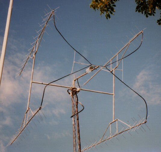
Figure 3. X-yagis mounted with glass-fibre tubes 0.8 m away from a metal tube that is parallel to the boom tube. | |
|
When mounting antennas on glass fibre tubes and bringing the feed cable out behind the reflectors it is necessary to keep some distance between the cable and the reflectors. Figure 4 shows the gain of a 2SA13X fed with equal power into both polarisations for generation of a vertically (or horisontally) polarised wave. The boom tube is extended behind the reflectors by different lengths and a tube of diameter 20 mm is routed in an angle of 45 degrees, parallel to one of the reflectors towards what would be the center point in an array of four antennas. This tube represents the coaxial cables and the length of this tube affects the interaction with the antenna. The length of the tube simulating the cables affects the interaction, the cable forms an extra (half) reflector and the current flowing on it will depend on its length. It will be difficult to simulate the real behaviour with cables because the cables are covered by a dielectric that changes the wave speed. Figure 4 shows that a distance of 200 mm is sufficient to make the gain loss below 0.1 dB even if the length of the cables becomes unfavourable. The data for figure 4 is here: cable.txt Cables that go from the end of the boom tube to a center point for a 4-yagi array need mechanical support. For this purpose an extra reflector in electrical contact with the boom tube can be added behind the ordinary reflector. The cables can then be tied to this extra element to avoid mechanical stress at the cable bend. Such an extra "support rod" will serve as a stub on the transmission line formed by the cable and the boom tube and such a stub will reduce the coupling to the field behind the reflector. Such a "support rod" that extends 537 mm on the opposite side of the cable weakens the interaction between the cable and the antenna as shown in figure 5. Already at a distance of 150 mm behind the reflector the length of the cable only changes the gain by 0.03 dB between the best and the worst length. Compared to the free space gain, the gain loss 150 mm behind the reflector is only 0.04 dB for the worst cable length. The data for figure 5 is here: cablestub.txt and the NEC input file is here: cablestub.nec The simulations were made with NEC4. Removing the stub from this input file gives the input for the simulations for figure 4. Simulations for an array of four 2SA13X antennasThe simulations for a single antenna indicate that the 2SA13X can be mounted on metal tubes in electrical contact with the boom tube if the mounting point is carefully choosen. Figure 6 shows the gain of such a design at different mounting points. The data for figure 6 is here: fourstack_metalh.txt and the NEC input files are here:fsmh_vpol.nec fsmh_45pol.nec fsmh_hpol.nec These simulations indicate that the 2SA13X could be mounted on a metal stacking H with acceptable losses if the mounting point is 3550 mm from the reflector. The gain loss due to interaction with the metal structure seems to be less than 0.2 dB but the accuracy of this result is hard to judge. Isolated mounting with cables coming out behind the reflectors has the advantages of shorter cable lengths (to the receive pre-amplifier) and much less coupling to metal structures and consequently a much lower risk that errors in the simulation would lead to higher losses than predicted by the simulations. With the pre-amplifiers on an extra support tube in the center of the array one also has the advantage of easy access to pre-amplifiers and rx/tx switches by pointing the antenna into the sky with 90 degree elevation. The pre-amplifiers are then close to the tower at a height about 3.5 m below the rotors. This is an advantage if the tower is not very high. Simulation of a four-stack of 2SA13 with cables and stubs behind the reflectors and with a support tube parallel to the boom tube would be very time consuming if a straightforward input file like the ones used for figure 6 were used. The problem is that a very large number of segments has to be used both for the boom tubes and for the antenna elements to avoid simulation errors in the interaction between the boom tube and the elements. The reason is that the separation between the boom tube and the elements is very small. These problems can be avoided by simulating the boom tube and the elements with segments that cross symmetrically with respect to the crossing point. This can be done by simulating the boom tube with a large number of series connected wires, each one placed symmetrically around an element. Likewise the elements can be simulated with several series connected wires that have segments that are symmetrical with respect to the neighbouring orthogonal wire as well as to the boom tube. The NEC input file becomes much more complicated but accurate NEC4 results are obtained with a much lower number of segments for the entire structure. Figure 7 shows the simulated gain for a four-stack of 2SA13X connected for four different polarisations in steps of 45 degrees. In figure 7 the coaxial cables and a stub that extends the cable across the boom tube 200 mm behibd the reflector is included. The figure shows the gain with the mounting point and the length of the support tube as parameters with the separation between boom tubes and the support tubes fixed at 800 mm. From figure 7 we can see that the optimum mounting point is about 3200 mm from the midpoint between the two reflectors for a length of the support tube of 1200 mm. The maximum on the gain vs mounting point function is very broad compared to the direct mounting on a metal tube shown in figure 6. The simulation error for the loss due to interaction with the boom tube is below 0.05 dB. The gain loss should be zero within the NEC model since only axial currents are included. The addition of cables and stacking tubes cause small deviations from the gain with boom tube allone in the optimum configuration. This most probably indicates that the gain of the real world antenna with all its metal does not differ from a real world antenna mounted entirely on isolators for boom tubes as well as for the stacking framework by more than a few hundredths of a dB. The data for figure 7 is here: fourstack_all.txt and the NEC4 input file to produce figure 7 is here: fsall.nec Since the influence of the support structure and the cables is smaller than the errors in the interaction between the boom tubes and the elements figure 7 might look like it does not really allow a definite conclusion on the optimum geometry. The gain is more dependant on how the structure is excited than on the geometry of the stacking harness. Adding the stacking structure and the cables to elements and boom tubes is however a very small perturbation and therefore the shapes of the four curves should be reasonably accurate even if there are errors in the absolute gain that differs depending on the polarisation. The small currents on the stacking tubes, booms and cables do not change the relation between the currents in the elements in the first order. Therefore the mechanism causing gain loss is that some energy is lost to the structure. What happens with the energy afterwards is irrelevant for the forward gain and therefore it is possible to magnify the effects of the undesired couplings by making the tubes and cables lossy. Figure 8 shows the same thing as figure 7 but for figure 8, the boom tube and the stacking and support tubes are loaded with a conductivity that is 1000000 times worse than that of aluminium. The cable is also loaded except for a short length opposite to the "stub" which is also not loaded. Currents on the extra element behind the reflector are harmless because they radiate essentially in the same way as currents on the reflector. The lossy structure dissipates energy more efficiently and therefore it loads the antenna more, causing the gain maxima in figure 8 to become sharper as compared to figure 7. The geometry of minimum gain loss is the same as expected. The data for figure 8 is here: fourstack_all_loaded.txt and the NEC4 input file to produce figure 8 is here: fsall_loaded.nec The optimum length of the "stub", the extra 6 mm element 200 mm behind the reflector was determined from single antenna simulations to be 537 mm. Changing the end coordinates of the stub from (2480,2480) by 20 mm in either direction causes the gain to drop between 0 and 0.005 dB for all polarisations. As expected the optimum length of the stub does not depend on interactions with other antennas or stacking tubes. The influence of a tower on a four-stack of 2SA13XAntennas are mouinted in towers and we have to simulate the influence of the tower to be sure that the whole system works as intended. Figure 9 shows the gain as a function of the elevation angle for a four-stack of 2SA13X mounted with cables and stacking tubes as found to be optimal above. In figure 9, three different side lengths for the tower are simulated. It is not surprising that a tower with a side length of 1 m (o.5 wavelength) causes a significant degradation. It is also nice to know that a tower with a side length of 0.25 m has negligible influence on performance. The data for figure 9 is here: tower.txt and the NEC4 input file to produce figure 9 is here:tower.nec |